
Testing
The main modification done to the shredding and gearing components was changing the previous chain drive into a synchronous belt drive. The purpose of the testing process is to meet the requirements of cutting carbon fiber with the replacement of a synchronous belt. The first test will measure the speed of the belt drive for the gearing component using a tachometer. Data will be documented based on design requirement #2 in the engineering report, which states that the motor, for the gearing portion, must achieve a minimum of 1000 RPMs. The second test procedure will measure the sound of the machine with a sound level meter. This test is based on design requirement #3 in the engineering report which states that the sound of the machine must be reduced by 50%. The last test that will be conducted is measuring the length of each carbon fiber strip after it exists the crusher and shredder. This test is based on design requirement #6 which states that the material size exiting the shredder must be 0.75 +/- 0.15 inches long.
One complication that occurred during the testing process was that the purchased belt for the shredder was excessively long when it arrived. In the Fall, the belt length for the shredder was calculated using the center-to-center distance of 30.44 inches between the shafts and the pitch diameters of a 38-teeth sprocket and a 112 teeth sprocket. The calculated belt length was 75.7 inches which was too long. The solution to this was to order the same size belt as the gearing component and make the center distance between the shafts 25.5 inches as well.
First Test Process: Measuring the RPMs on the driven sprocket for the speed reducer.
This procedure documents the process of using a tachometer to measure the RPMs of the shaft on the speed reducer. The previous chain sprockets on the speed reducer had a 1:1 ratio. The current design of the speed reducer has synchronous belt sprockets with a 3:1 ratio. The 3:1 ratio for the sprockets on the speed reducer is designed to achieve a minimum of 1000 RPMs to operate the machine. The following is the test information and procedure.
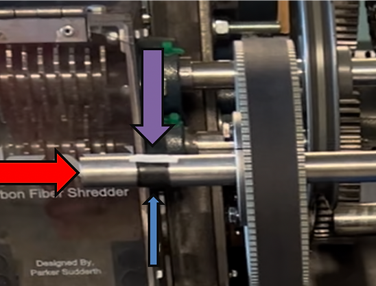
Figure 7: Test Set up Explained
-
Red Arrow - shaft for the speed reducer
-
Blue Arrow - black tape around the shaft
-
Purple Arrow - a strip of white tape across the black tape

Figure 8: Tachometer pointing directly at the white tape while the machine is operating.
Second Test Process: Measuring the sound of the machine
A tachometer is an instrument that measures, in revolutions per minute, the working speed of a machine. The tachometer was used in the first test procedure to measure the RPM on the driven sprocket, sprocket on the speed reducer shaft, for the gearing component. The test was conducted with the driving sprocket, sprocket on the motor shaft, at three different speeds which were 1000 RPM, 1240 RPM, and 1425 RPM. By using the linear velocity equation, the performance prediction for each speed on the driven sprocket was 339 RPM, 420 RPM, and 483 RPM. The results from the tachometer readings can be found in the results section.
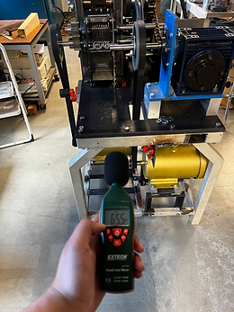
Figure 9: Sound Meter Device being used 2 ft. from the crusher entrance.

Figure 10: measuring the sound from the side of the shredder.
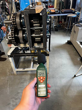
Figure 11: Sound Meter Device being used 2 ft. from the crusher entrance.
Third Test Process: Measuring the length of each carbon fiber strip
A ruler was used to measure the length of each carbon fiber strips from the first batch. The average length of each carbon fiber was 4.17 centimeters which equates to 1.64 inches.
Video 5: Carbon fiber being crushed and shredded

Figure 10: sample size of 8 pieces of carbon fiber